Outlet Testing Robot
Written on March 28th, 2025 by Paul Dreyer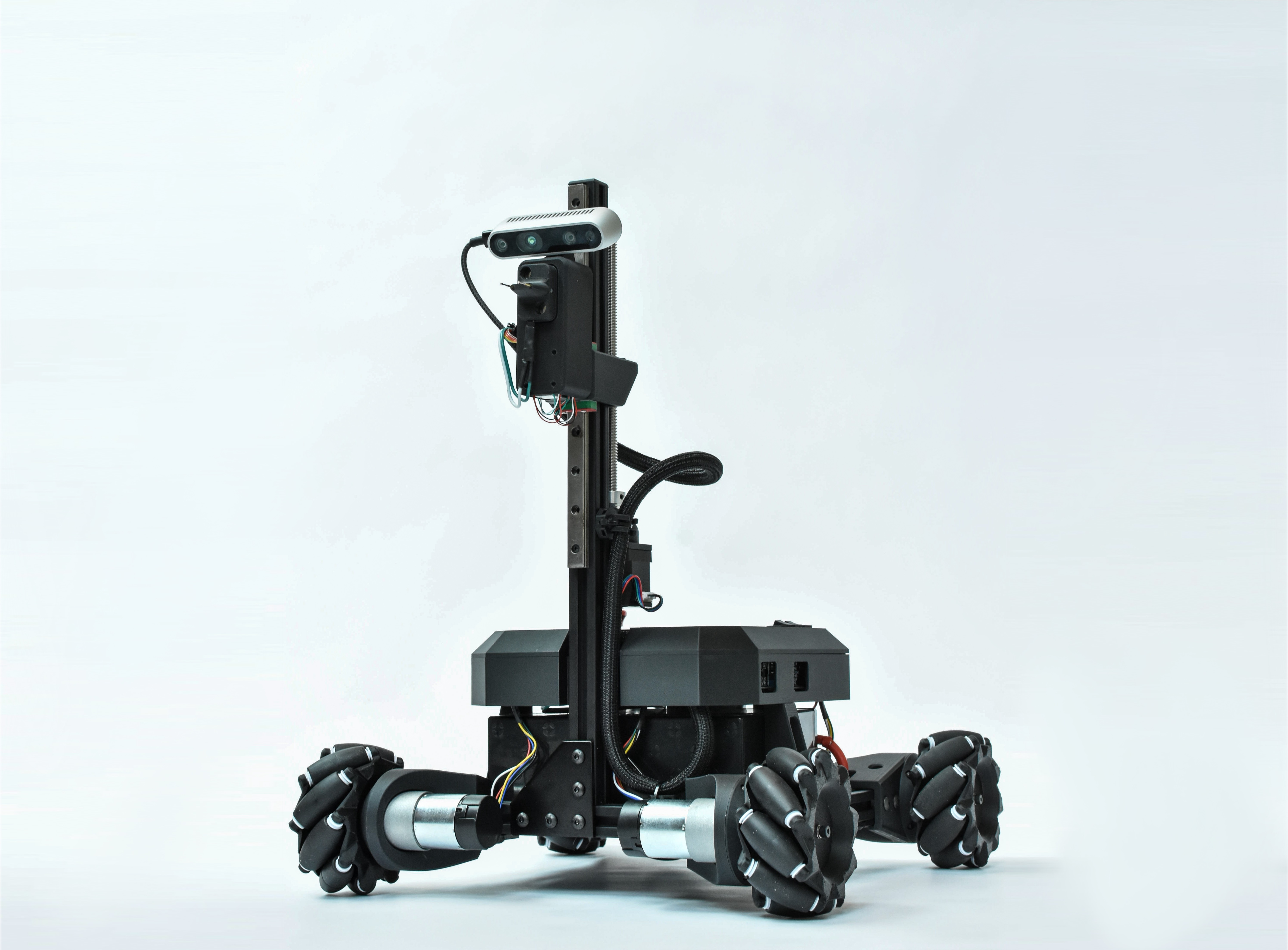
Background
This is a robot which autonomously explores a room / corridor and tests each outlet for functionality. The use case here is demonstrating an ability for a robot to self-dock for recharging in an arbitrary room without the need for a custom charging base.
Design Considerations
Testing The Outlet
In order to traverse a flat room and test outlets, we need to be able to move a probe head around the space with four degrees of freedom: X, Y, Z (height from ground), and Theta (the orientation angle). I chose to use a mecanum wheel setup as our translation system, as this allows for omni- directional travel of the robot base in X, Y, and Theta, which means we can pose the robot in any position and orientation we want to without kinematic restrictions. Now, instead of needing a multi- axis actuator to handle the variable outlet heights, we only need to account for Z which lead me to design a single degree of freedom actuator to move the probe head, changing its height from the ground.
Sensing The Environment
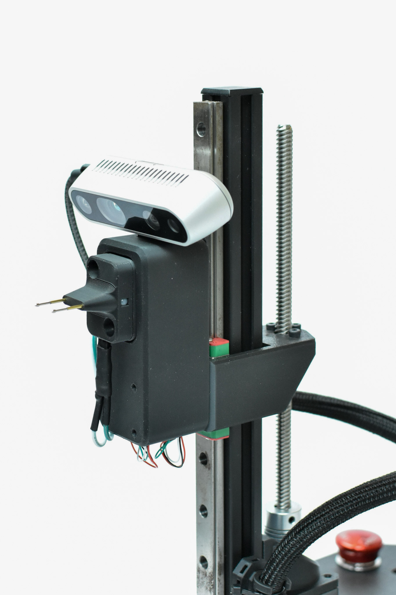
In order to actually plug in and test an outlet, we need to be able to gain environmental information for the robot to make decision on. Our primary sensor that enables perception is our D435 camera, which is mounted to the tool head. The camera can simultaneously provide point cloud data from its active stereo suite which allows us to gain an understanding of distances to objects in the environment, as well as photos of the forward view of the robot. We can then inference a custom trained Yolo-V8 model on the photos the D435 captures to predict outlet locations.
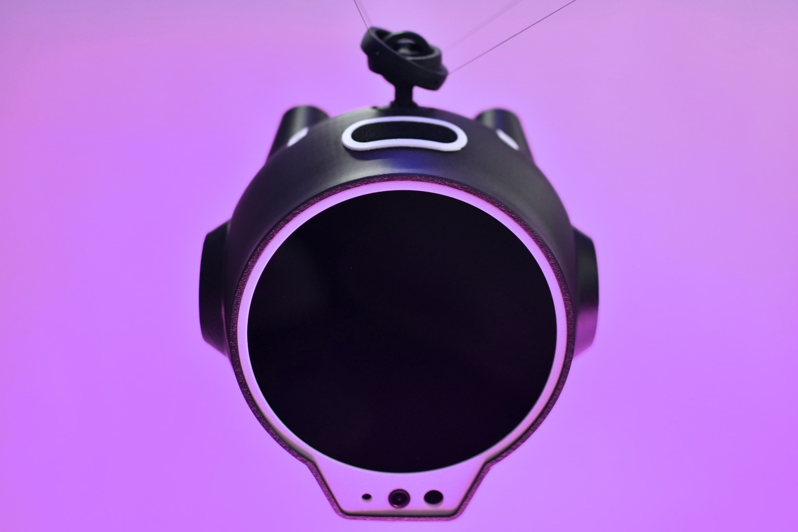
The tool head is equipped with two conductive “pogo-pin” probes, which conduct the current from the outlet to our AC voltage sensor on board. The probes are mounted on a ‘break-away’ surface at the end of a load cell in the tool head, which allows us to sense the axial force applied to the test probes. This enables the robot to sense if the probes are in contact with the outlet, and stops advancing if a safe limit force is experienced. For additional saftey, the probes are able to ‘break-away’ from the tool head, when the magnetic force holding them to the tool head is exceeded. This is designed to allow them to shear from the robot in the event that our trajectory planning or tracking experiences errors that could damage the probes.
Finally, the robot is also equipped with encoders on each drive motor, as well as an inertial measurement unit (IMU) onboard for simultaneous localization and mapping (SLAM) closure.
Contributions
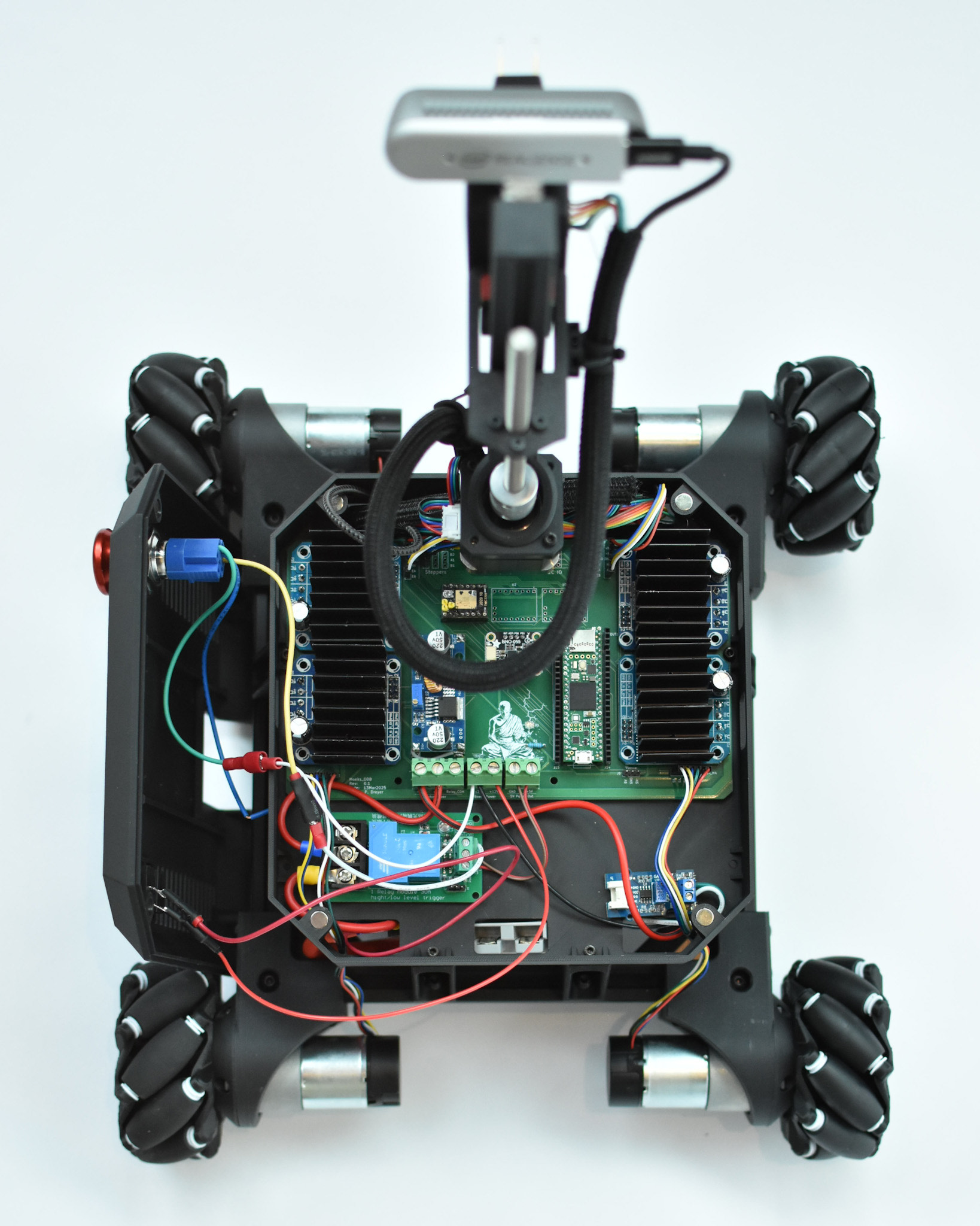
I owned the mechanical / electrical efforts for this project. I designed, fabricated, and tested the mecanum wheel sub assemblies, the vertical cantry system, and the break-away tool head system. I also developed the main circuit board for the robot, which accounts for sensor IO routing, power distribution, and motor output routing.
When I finished the physical build of the robot, I developed scripts to define the kinematics of the platform and trajectory design, allowing us to leverage the truly omni-directional capability of the robot to achieve efficient sensor sweeping motions as it explores the environment for new outlets to test.